The Modelling Language
Since ADOit® follows a meta-model based approach a variety of modelling concepts can be used within the tool. The specific modelling language used in the project is briefly described below. It is based on the set of standard modelling languages of ADOit® as a part of the BOC Architecture Management Framework (see ENISA RM Framework) and was modified according to the specific requirements of the project.
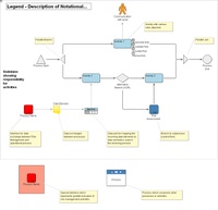
 The figure on the right shows a legend which is included as an additional diagram within the set of models which forms the main deliverable of the project. On the top of the diagram an exemplary process model is displayed, including a process start (triangular shape Process Start), followed by a parallel branch (triangular shape pointing to the left) of the control flow (black arrows). After the branch two activities (Activity 1 and Activity 2) are executed concurrently. Communication to actors, i.e. in our case usually external roles, is expressed by data flows (lines with solid arrowhead). In the example a data flow to the actor symbol above Activity 1 is shown.
The diamond shaped symbol after Activity 2 represents an alternative branch, i.e. depending on the condition at the branch (e.g. a question, which can be answered with yes or no) only one of the following paths will be followed. On the right hand side the parallel control flows are merged again with the triangular shape pointing to the right. The circular Process End symbol marks the end of the process execution. Roles involved in a process execution are annotated to the right of the respective activity. In the modelling of the particular processes in the project we distinguish between responsible (role that executes the process), accountable (role that is accountable for the outcome), consulted (role that gives advice) and informed (role that has to be briefed about the results of an activity). To the right of Activity 1 some exemplary roles are attached. The letters R, A, C and I indicate the type of the role attached (RACI notation, this way of describing role relations is e.g. used in the CobiT documentation).
The blue sub-process symbol which is connected to the alternative branch and Activity 3 represents another process model (here Risk Assessment) which is invoked at the position of the sub-process symbol. By using this model element the graphical complexity of a diagram can be reduced. To the left of the figure a red interface object is shown. The text below the symbol shows the name of the process which contains the related interface (in this case Process Name). Every interface of this type is connected to exactly one interface of the same type in another process. These interfaces are used for showing the information flow between the Risk Management processes on the one hand and the operational processes on the other hand. The exchanged data elements are represented by yellow document-like symbols (Data Element). Every incoming data element is mapped to one or more data elements inside the Data Port.
The whole exemplary process is arranged inside a level or swimlane, which is used to display a role or organisational unit responsible for the included part of the process. Every activity is assigned to zero or one swimlanes.
On the bottom of the figure two additional model objects are displayed. To the left a special interface in front of a red box can be seen, which shows the parallel execution of Risk Management activities in the connected processes. Whenever this interface is used, data is exchanged between an activity of the Risk Management framework and an activity in an operational process, which also deals with Risk Management, i.e. usually in terms of operational risks.
The model object to the right of the above described interface is the process symbol. This object stands for a process in a process map and therefore is linked to a diagram containing a process model (with activities and control flows) or another process map (with processes). Finally, the light yellow boxes connected to the other model elements by a dotted line contain commentaries which contribute by providing additional semantics to the models.

